💡 Direct Answer & Executive Summary (Inductance of Solenoid Calculator)
Definition: Compute values for Inductance of Solenoid Calculator in standard SI units physics.
Governing Math Formula: Physical equation system model for Inductance of Solenoid Calculator.
Target Applications: Provides real-time quantitative solutions in Physics & Engineering for students, engineers, researchers, and finance professionals.
Inductance of a Solenoid Calculator ()
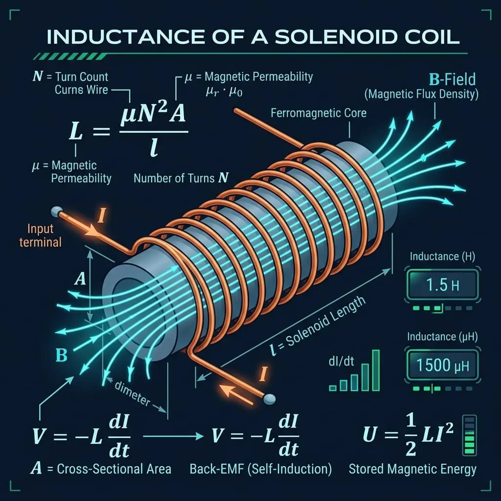
1. Introduction
From the high-frequency toroidal chokes filtering electrical noise inside laptop power supplies to the multi-tesla superconducting magnet coils guiding relativistic subatomic particle beams in CERN's Large Hadron Collider, and the electromagnetic solenoids actuating fuel injectors and starter motors in automotive engines, Inductors and Solenoid Coils are fundamental pillars of electromagnetism.
While a capacitor stores energy in an electric field through accumulated charge (), an inductor stores energy in a magnetic field () generated by flowing electric current ().
The fundamental physical property of an electrical conductor or coil to oppose any sudden change in electric current by generating a counter-electromotive force (Back-EMF) is known as Inductance ().
graph LR
    N["🌀 Coil Turns (N)
Squared Multiplier (N²)"] --> MULT["✖️ Geometry & Core"]
    MU["🧲 Core Permeability (μ)
μ = μ_r · μ₀"] --> MULT
    A["📐 Core Area (A)
Cross Section (m²)"] --> MULT
    L_LEN["📏 Solenoid Length (l)
Axial Length in Meters"] --> DIV["➗ Divided By"]
    MULT --> DIV
    DIV --> L["⚡ Inductance (L)
L = (μ · N² · A) / l (Henries H)"]
    L --> U["💡 Stored Magnetic Energy
U = ½ · L · I² in Joules (J)"]
    L --> EMF["🛑 Faraday-Lenz Back-EMF
V_L = -L · (dI / dt)"]
Mastering solenoid inductance calculations allows electrical engineers, roboticists, and physicists to:
- Design high-efficiency switch-mode power supply (SMPS) buck/boost converter inductors.
- Engineer electromagnetic relays, solenoid valves, and robotic linear magnetic actuators.
- Size inductive filtering chokes to suppress electromagnetic interference (EMI) and radio frequency interference (RFI).
- Tune LC resonant radio frequency tank circuits for wireless communications and impedance matching networks.
- Design wireless inductive charging coils for smartphones and electric vehicle charging pads.
2. Definitions & Analogies
2.1 The Simple Definition
In simple everyday terms:
- A Solenoid is a long, tightly wound helical coil of insulated wire (like an elongated metal spring).
- Inductance () is the "electrical inertia" of the coil (measured in Henries, ).
- Just as a heavy flywheel resists sudden changes in rotational speed (it takes time to spin up and time to slow down), an inductor resists any sudden change in electric current.
- If current tries to jump up suddenly, the inductor generates a reverse voltage (Back-EMF) to push back; if current drops suddenly, the inductor collapses its stored magnetic field to keep the current flowing.
2.2 The Formal Technical Definition
Definition of Self-Inductance via Faraday's & Lenz's Laws
Formally, self-inductance () is the constant of proportionality between the induced counter-electromotive force ( or ) in a circuit and the time rate of change of electric current ():
Where:
- is the induced back-EMF in Volts ().
- is the self-inductance in Henries ().
- is the total number of wire turns.
- is the magnetic flux passing through each turn in Webers ().
- The negative sign ($-$) reflects Lenz's Law: the induced voltage always acts to oppose the change in magnetic flux that produced it.
Solenoid Geometric Inductance Equation
For an ideal cylindrical solenoid of length (), cross-sectional area (), and turn count () wound on a core of magnetic permeability ():
Where:
- is the Vacuum Magnetic Permeability Constant.
- is the dimensionless Relative Permeability of the core material.
- is the total number of coil turns.
- is the axial length of the solenoid in meters (), assuming length is much greater than radius ($l \gg r$).
- is the cross-sectional area of the solenoid core in square meters ().
- is the turn density (turns per meter).
- is the internal volume of the magnetic core ().
2.3 The Water Wheel / Heavy Turbine Inertia Analogy
To build an intuitive physical mental model, compare electric current passing through an inductor to water flowing through a pipe containing a heavy paddle wheel attached to a massive flywheel:
graph TD
    subgraph Hydraulic_Inertia ["💧 Hydraulic Flywheel Turbine Analogy"]
        Valve["Open Valve (Sudden Flow)
Heavy wheel resists, flow starts slowly"]
        Steady["Steady State Speed
Wheel spins smoothly, ZERO resistance"]
        CloseValve["Slam Valve Shut (Sudden Stop)
Spinning wheel keeps pumping water, causing pressure spike!"]
        Valve --> Steady --> CloseValve
    end
    subgraph Electric_Inductance ["⚡ Electrical Inductor Solenoid"]
        SwitchOn["Switch Closed (Current Rises)
Back-EMF fights voltage, current ramps up slowly"]
        SteadyDC["Steady DC Flow (dI/dt = 0)
Zero back-EMF, coil acts like simple low-resistance wire"]
        SwitchOpen["Open Switch (Current Drops)
Collapsing B-field creates massive high-voltage spark!"]
        SwitchOn --> SteadyDC --> SwitchOpen
end- Starting Current: When you open the valve, the heavy paddle wheel resists spinning up instantly, creating a back-pressure that limits initial water flow. In an inductor, the rising magnetic field generates a Back-EMF that forces current to ramp up gradually according to an exponential curve ().
- Steady State: Once the flywheel is spinning at full speed, it offers zero resistance to the steady flow of water. Similarly, an inductor offers zero resistance to pure steady DC current (aside from the tiny DC wire resistance ).
- Interrupting Current (Inductive Kick): If you slam the valve shut instantly, the momentum of the spinning flywheel tries to keep forcing water forward, creating a massive hydraulic water-hammer pressure spike! In an electrical circuit, breaking an inductive current suddenly causes the magnetic field to collapse almost instantaneously (), generating a destructive high-voltage inductive spike (often thousands of Volts) that arcs across open switch contacts unless clamped by a flyback diode.
4. History & Milestones in Inductance & Electromagnetism
timeline
    title Milestones in Inductance & Electromagnetic Induction
    1820 : Hans Christian Ørsted discovers that electric currents create magnetic fields
    1820 : André-Marie Ampère invents the helical solenoid coil and formulates Ampère's Law
    1831 : Michael Faraday discovers Electromagnetic Induction in London
    1831 : Joseph Henry independently discovers Self-Inductance in Albany, New York
    1834 : Heinrich Lenz formulates Lenz's Law of induced opposition
1890s : Nikola Tesla builds high-frequency resonant air-core Tesla Coils- Ampère's Helical Solenoid (1820): Immediately after Ørsted observed a compass needle deflect near a live wire, French physicist André-Marie Ampère wound wire into a tight helix, coining the scientific term Solenoid (from the Greek solen, meaning "channel" or "pipe"). He proved that a current-carrying coil creates a uniform internal magnetic field identical to a permanent bar magnet.
- Joseph Henry & Self-Inductance (1831): American scientist Joseph Henry built the most powerful electromagnets of his era by wrapping insulated silk wire in dense multi-layer coils. He discovered that when a long coiled circuit was broken, a bright spark leaped across the gap—discovering Self-Induction. In 1893, the International Electrical Congress formally named the SI unit of inductance the Henry () in his honor.
- Heinrich Lenz (1834): German-Russian physicist Heinrich Lenz established the conservation-of-energy rule for induced voltages: the induced current always flows in such a direction that its own magnetic field opposes the original magnetic flux change that created it.
5. Core Concepts & Parameters Explained
5.1 Coil Turns Count () and the Quadratic Multiplier
- Definition: The total number of complete circular loops of wire wound along the solenoid.
- Quadratic Scaling (): Notice that turn count is squared in the inductance equation! This occurs because:1. Adding more turns increases the internal magnetic field strength: .2. The total magnetic flux links through all turns: .- Engineering Rule: Doubling the number of turns on a given core increases its inductance by (); tripling turns increases inductance by ()!
5.2 Core Cross-Sectional Area () and Length ()
- Core Area (): The perpendicular cross-sectional area enclosed by each loop of wire (). Larger core area captures more magnetic flux, increasing inductance linearly ($L \propto A$).
- Solenoid Length (): The axial length from the start to the end of the coil windings. Spreading the turns over a longer length weakens the internal magnetic field concentration, reducing inductance ().
5.3 Magnetic Permeability () & Core Materials
Inserting a ferromagnetic or ferrite core inside an air solenoid concentrates magnetic field lines, multiplying inductance by the core's Relative Permeability ():
| Core Material | Relative Permeability () | Saturation Flux Density () | Primary Industrial Application |
|---|---|---|---|
| Vacuum / Air | $1.00000$ | (Never saturates) | RF radio tuning coils, non-saturating chokes |
| Wood / Plastic / Glass | N/A | Non-magnetic structural coil bobbins | |
| Aluminum (Paramagnetic) | $1.00002$ | N/A | Shielding cans |
| Ferrite (MnZn - Manganese Zinc) | SMPS power inductors, high-frequency filters () | ||
| Ferrite (NiZn - Nickel Zinc) | VHF radio frequency chokes, EMI suppression beads | ||
| Silicon Steel (Transformer Steel) | utility power transformers, heavy motors | ||
| Permalloy () | Precision audio transformers, magnetic shielding | ||
| Supermalloy | Ultra-sensitive fluxgate magnetometers | ||
| Nanocrystalline Amorphous Alloy | EV traction inverters, renewable energy filters |
5.4 Stored Magnetic Energy ()
The energy stored in an inductor's magnetic field is proportional to the square of the flowing electric current:
- SI Unit: Joule ().
- Physical Meaning: Unlike a resistor which dissipates energy into heat, an ideal inductor stores energy in its magnetic field without losses, returning that energy to the circuit when the current decreases.
6. The RL Circuit Time Constant ($\tau$) & Inductive Reactance ()
graph LR
    L_VAL["⚡ Inductance (L)
Henries (H)"] --> DIV_RL["➗ Divided By"]
    R_VAL["🛑 Resistance (R)
Ohms (Ω)"] --> DIV_RL
    DIV_RL --> TAU_RL["⏱️ RL Time Constant (τ)
τ = L / R (Seconds)"]
6.1 RL Time Constant ()
When DC voltage () is connected across a series resistor-inductor circuit, current ramps up exponentially toward its Ohm's Law maximum ():
- At : Current reaches 63.2% of maximum.
- At : Current reaches 99.3% (steady state DC).
6.2 Inductive Reactance in AC Circuits ()
In an AC circuit with frequency (), an inductor continuously opposes current oscillations, creating Inductive Reactance ():
Higher frequencies produce higher impedance, making inductors ideal for Low-Pass Filters that block high-frequency noise while passing low-frequency DC signals.
7. Master Formula Matrix & Step-by-Step Problem Solver
| Unknown Variable | Primary Formula | Formula Given Core Density () | Formula Given Stored Energy () |
|---|---|---|---|
| Inductance () | |||
| Number of Turns () | |||
| Core Area () | |||
| Solenoid Length () | — | ||
| Stored Energy () | — | — | |
| Induced Back-EMF () | — | — |
8. Practical Real-World Calculation Examples
Example 1: Air-Core Radio Tuning Solenoid
- Scenario: An RF engineer winds an air-core radio tuning coil with of fine enameled wire on a plastic cylinder (). The circular cross-sectional area is . Air core (, ).
- Step 1: Calculate Geometric Quantities:
- Step 2: Calculate Inductance ():
Example 2: Ferrite-Core Power Supply Filter Inductor
- Scenario: The same physical coil geometry (, , ) has a high-permeability Manganese-Zinc (MnZn) ferrite rod inserted into its core ().
- Calculated Ferrite-Core Inductance:(Inserting the ferrite rod increased the inductance by , turning a micro-inductor into a heavy-duty power filter!).
Example 3: Stored Magnetic Energy in an MRI Superconducting Solenoid
- Scenario: A clinical Magnetic Resonance Imaging (MRI) scanner uses a liquid-helium cooled niobium-titanium superconducting solenoid with total self-inductance energized with a persistent current .
- Stored Magnetic Energy Calculation:
- Equivalent Explosive Energy: is equivalent to the chemical energy of approximately ! In the event of an emergency magnet quench (sudden loss of superconductivity), this energy must be safely vented as boil-off gaseous helium.
Example 4: Inductive Kick Back-EMF Voltage Spike
- Scenario: A automotive transmission solenoid valve with inductance draws . A mechanical relay opens, cutting the current to zero in .
- Calculated Back-EMF Voltage Spike ():
- Engineering Consequence: A circuit generated a reverse spike, which would instantly vaporize controlling transistors unless protected by a parallel flyback diode.
Example 5: Determining Required Turns for a Target Inductance
- Scenario: An electronics hobbyist needs to build a air-core inductor on a cardboard tube () with winding length ().
- Calculation of Required Turns ():
9. Real-World Engineering Case Studies
Case Study 1: Flyback Diode Protection in Automotive Relay Actuators
- Problem Background: Modern vehicle Engine Control Units (ECUs) use N-channel MOSFET semiconductor transistors to pulse-width modulate () inductive solenoid fuel injectors (, , ).
- The Failure Mode: When the MOSFET turns OFF in , the collapsing magnetic flux generates an instantaneous back-EMF spike:In reality, the MOSFET drain-to-source avalanche breakdown voltage () is exceeded within nanoseconds, puncturing the silicon gate oxide and permanently shorting the ECU.
graph LR
    subgraph Flyback_Circuit ["🛡️ Flyback Diode Protection Circuit"]
        V_IN["+12V Supply"] --> COIL["⚡ Solenoid Coil (L, R)"]
        COIL --> DRAIN["MOSFET Switch (GND)"]
        DIODE["🛡️ Parallel Flyback Diode (1N4007)
(Connected in Reverse-Bias across Coil)"]
        COIL -.->|"Circulates Clamped Current on Turn-Off"| DIODE
end- Engineering Solution: Connecting a fast-recovery diode (such as a Schottky diode) in reverse-bias directly across the solenoid terminals creates a closed free-wheeling recirculation loop. When the transistor opens, the inductive current circulates harmlessly through the diode, clamping the voltage spike to safely , completely protecting the ECU.
Case Study 2: Switch-Mode Power Supply (SMPS) Buck Converter Energy Storage
- Application Context: A computer motherboard steps down an incoming power supply rail to to power a multi-core CPU, delivering a continuous DC current of at a switching frequency ().
- Inductor Function: A high-current powdered-iron toroidal inductor stores magnetic energy during the switch ON-time and smoothly discharges it to the CPU during the switch OFF-time.
- Design Parameters:- Input Voltage: , Output Voltage: .- Duty Cycle: (10%).- Allowable Peak-to-Peak Ripple Current ().
- Calculated Required Inductance ():
- Result: The ultra-low multi-phase surface-mount ferrite inductor maintains rock-steady millivolt regulation across rapid nanosecond CPU load changes.
10. Common Mistakes & How to Avoid Them
Mistake 1: Ignoring Core Magnetic Saturation ()
Driving too much DC bias current through an iron or ferrite core inductor. When magnetic flux density exceeds the saturation limit (), the relative permeability abruptly drops to (air). The inductance crashes by 99%, causing catastrophic current spikes that burn out switching transistors!
Mistake 2: Linear Turns Misconception ( vs. )
Assuming that doubling the turns doubles the inductance. Because both magnetic field and flux linkage scale with , inductance scales with ().
Mistake 3: Unshielded Magnetic Flux Crosstalk
Placing two open air-core solenoids side-by-side on a printed circuit board. Stray magnetic field lines from one inductor link through the other, creating mutual inductance () noise interference. Always orient adjacent coils at right angles or use shielded toroidal cores.
11. Frequently Asked Questions (FAQ)
Q1: What is the fundamental difference between an inductor and a capacitor?
A: - Inductors store energy in a magnetic field () via moving electric current (), and resist sudden changes in current.
- Capacitors store energy in an electric field () via static electric charge (), and resist sudden changes in voltage.
Q2: What is the physical meaning of 1 Henry ()?
A: An inductor has a self-inductance of if an electric current changing at the rate of induces a counter-electromotive force (Back-EMF) of across its terminals.
Q3: Why does a solenoid need a high length-to-diameter ratio ($l \gg d$) for the standard formula to be accurate?
A: The standard formula assumes an infinitely long ideal solenoid where the internal magnetic field is perfectly uniform and external fringing fields at the ends are negligible. For short coils (), Nagaoka's coefficient correction factor () must be applied to account for end-leakage flux.
Q4: What is Mutual Inductance ()?
A: Mutual inductance occurs when the changing magnetic field of one coil induces an EMF in an adjacent secondary coil (). This is the operating principle behind electrical transformers, wireless smartphone charging pads, and guitar pickups.
Q5: What are Eddy Currents and how do laminated cores reduce them?
A: Alternating magnetic flux induces swirling parasitic electrical currents (Eddy currents) inside solid conductive metal cores, causing massive Joule heat losses (). Transformers and solenoids use thin insulated silicon steel sheets (laminations) or non-conductive ferrite ceramic powders to break up conductive loops, eliminating eddy losses.
Q6: What is a Toroidal Inductor vs. a Cylindrical Solenoid?
A: A toroidal inductor is a donut-shaped core with wire wrapped around its ring. Because the magnetic flux forms a continuous closed circle inside the core with zero open ends, toroidal inductors have virtually zero external magnetic flux leakage, preventing EMI noise from radiating to nearby circuits.
Q7: What is Inductive Reactance () and how does frequency affect it?
A: Inductive reactance () is the effective AC resistance of an inductor in Ohms. At (DC), (acts like a short circuit / pure wire). At ultra-high frequencies (), (acts like an open circuit), making inductors natural high-frequency filters.
Q8: What is the Skin Effect in high-frequency coil windings?
A: At high AC frequencies, internal self-induced eddy magnetic fields push flowing electrons toward the outer perimeter of the copper wire (the "skin"), reducing effective cross-sectional area and increasing AC resistance. RF inductors use multi-strand braided Litz wire or hollow silver-plated copper tubes to minimize skin effect losses.
12. Expert Tips & Best Practices
- Always Include Flyback Diodes Across Inductive DC Loads: Whenever driving relays, motors, or solenoid valves with microcontrollers or transistors, wire a fast-recovery diode antiparallel across the coil to clamp inductive back-EMF spikes.
- Select Gapped Ferrite Cores for High DC Bias Currents: When designing power supply filter chokes that carry large continuous DC currents, use cores with a small precision air gap to prevent magnetic core saturation.
- Convert Coil Dimensions to Meters Before Multiplying: Always convert millimeters () and square centimeters () before applying the permeability constant ().
13. Summary & Key Takeaways
- Fundamental Solenoid Inductance Formula: (measured in Henries ).
- Quadratic Turn Scaling: Inductance scales with the square of turn count ().
- Core Permeability Multiplier: High-permeability ferromagnetic or ferrite cores multiply inductance by thousands ().
- Stored Magnetic Energy: (stored in Joules ).
- Faraday-Lenz Opposition: Inductors generate a counter-electromotive force () that opposes current changes, creating the fundamental basis of transformers, electric motors, power filters, and wireless charging systems.
Additional Technical Guidelines & Measurement Standards
When conducting calculations for Inductance of Solenoid Calculator, maintaining quantitative precision and verifying input parameter boundaries is essential for reliable scenario evaluation. Always verify that raw numerical inputs are measured using standardized instrumentation, and double-check unit conversions prior to applying outputs in commercial, industrial, or academic projects.
For quantitative unit conversions and scientific calculations, always maintain at least four decimal places of precision during intermediate arithmetic stages before rounding final results. When preparing technical reports, laboratory documentation, or financial forecasts, cross-verify all output variables against established international measurement standards (such as SI, NIST, and ISO metric benchmarks) to guarantee consistent analytical rigor across all computational workflows.
MathsLover.com delivers this interactive solver 100% free of charge to foster global mathematical literacy, educational accessibility, and data-driven problem solving across scientific, technical, and academic communities worldwide.