💡 Direct Answer & Executive Summary (Wall Framing Studs Layout Calculator)
Definition: Compute building materials for Wall Framing Studs Layout Calculator projects.
Governing Math Formula: Engineering dimensional estimation formula for Wall Framing Studs Layout Calculator.
Target Applications: Provides real-time quantitative solutions in Construction for students, engineers, researchers, and finance professionals.
Wall Framing Studs Layout Calculator: Complete Timber Framing Estimating Guide
1. Introduction
Platform timber framing—also known as stick framing or light-frame wood construction—is the predominant structural framing system for residential houses, townhomes, and low-rise commercial buildings across North America and much of the industrialized world. Engineered from standardized dimensional lumber ( and SPF/Douglas Fir studs), a timber-framed wall functions as a repetitive vertical truss system designed to carry vertical gravity loads (roof rafters and second-story floor joists) and resist lateral forces (wind and seismic shear).
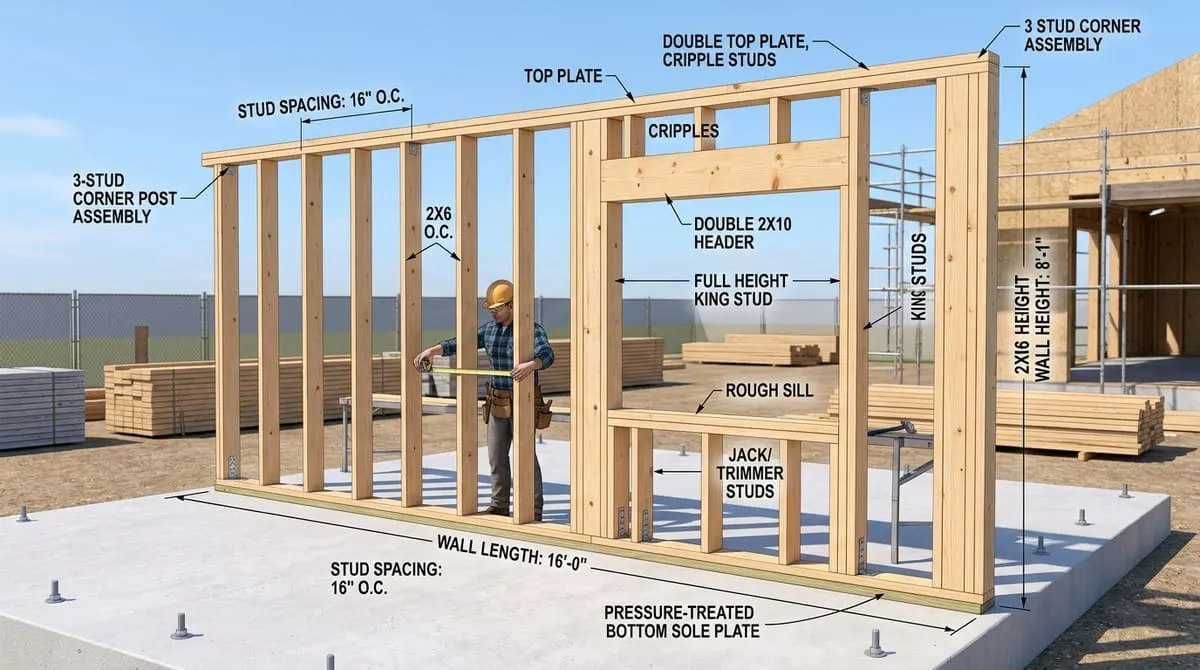
However, calculating the total lumber required for a framing layout involves far more than simply dividing the wall length by the stud spacing. A code-compliant structural wall requires top and bottom horizontal plates (typically 3 continuous plates per wall), multi-stud corner assemblies (3-stud corners or California corners), wall intersection partition T-posts, and rough opening framing (king studs, jack/trimmer studs, solid structural headers, and cripple studs).
flowchart TD
    LENGTH["📐 Wall Linear Length (ft)
Total Wall Run Measurement"] --> SPACING["📏 Stud Spacing Selection
16'' O.C. (Standard) vs 24'' O.C. (Advanced)"]
    SPACING --> BASE_STUDS["🌲 Base Common Studs
Studs = (Length / Spacing) + 1"]
    BASE_STUDS --> CORNERS["🏰 Corners & Intersections
+3 to +4 Studs per Corner / T-Wall"]
    CORNERS --> OPENINGS["🚪 Window & Door Rough Openings
+2 King + 2 Jack Studs per Opening + Cripples"]
    OPENINGS --> PLATES["📏 Horizontal Wall Plates
Bottom Sole Plate + Double Top Plate (3× Length)"]
    PLATES --> WASTE["🛡️ Add 10% Waste & Defect Factor
Lumber Warping, Bowing & Crown Sorting"]
    WASTE --> TOTAL_LUMBER["📦 Total 2×4 / 2×6 Studs & Plates to Order"]
Mastering wall framing mathematical layout enables carpenters, general contractors, framing crews, and DIY builders to:
- Accurately calculate common stud counts for and framing layouts.
- Calculate total lineal footage and piece counts for bottom sole plates and double top plates.
- Account for structural load transfers around doors, windows, headers, and corner intersections.
- Differentiate between interior non-loadbearing partition walls vs. exterior insulated structural walls.
- Minimize lumber yard returns and avoid warped, crowned, or defective stud shortages.
2. Definition & Core Concepts
2.1 The Simple Definition
- Stud: A vertical structural wood or metal member in a building wall, typically or , spaced at regular intervals to support wall sheathing, insulation, and drywall.
- On-Center (O.C.): The measurement from the exact centerline of one framing member to the centerline of the adjacent member (e.g., means center-to-center distance is exactly ).
- Sole Plate (Bottom Plate): The horizontal framing lumber anchored directly to the subfloor or foundation slab upon which all vertical studs rest.
- Double Top Plate: Two continuous layers of horizontal framing lumber nailed across the top of studs to tie walls together and support roof trusses or floor joists.
2.2 Technical Definition
Under the International Residential Code (IRC Chapter 6 - Wall Construction), prescriptive timber framing establishes axial load capacity, lateral wind shear bracing, and thermal envelope performance.
For a wall of linear length (in feet) and stud spacing (in inches, typically ):
The theoretical base count of common field studs () is:
Total required framing studs () incorporates additional structural elements:
Where:
- per corner post assembly.
- per interior partition "T" junction.
- () plus cripple studs.
- for 1 bottom plate and 2 top plates.
2.3 The Architectural Analogy
Think of wall framing like a bookshelf structure:
- The vertical studs are like the vertical divider uprights holding up the heavy books (roof and upper floors).
- The top and bottom plates are the horizontal top and bottom panels holding the uprights square and upright.
- When you cut out a space for a window or door, you remove some uprights; therefore, you must install a strong horizontal bridge (the header) supported by doubled vertical posts (jack and king studs) so the roof weight doesn't crush the window frame.
3. Historical Evolution of Wall Framing Systems
timeline
    title Milestones in Wood Wall Framing Architecture
    Pre-1830s : Heavy Timber Post-and-Beam with Mortise-and-Tenon joinery
    1832 : George Washington Snow invents Balloon Framing in Chicago using light 2x4s
    1920s : Platform Framing replaces balloon framing, introducing floor-by-floor fire stops
    1970s : 2x6 framing introduced for exterior walls to accommodate thicker R-19/R-21 fiberglass insulation
Modern : Advanced Framing (Optimum Value Engineering - OVE) with 24'' O.C. spacing and insulated headers- Heavy Timber Framing (Pre-1830s): Buildings were constructed from massive hand-hewn or oak timbers joined with chiseled mortise-and-tenon joints and wooden pegs. It required huge teams of skilled timber framers.
- Balloon Framing Invention (1832): In rapidly growing Chicago, builders used water-powered sawmills to produce light lumber assembled with machine-made nails. In balloon framing, continuous 2-story tall studs extended from foundation to roof, but lacked natural fire-stops.
- Platform Framing (1920s–Present): Platform framing builds one floor level at a time. Each story provides a flat working "platform" with built-in horizontal bottom and double top plates that serve as natural fire-stops between floors.
- Advanced Framing / OVE (Modern): Advanced framing increases stud spacing from $16''$ to , uses 2-stud California corners, and replaces solid wood headers with insulated headers to maximize thermal efficiency and reduce lumber consumption by .
4. Stud Spacing & Lumber Sizing Comparison Matrix
| Framing Specification | Actual Dimensions | On-Center Spacing | Studs per 100 Linear Feet | Primary Application | Thermal & Structural Notes |
|---|---|---|---|---|---|
| at | Interior partition walls, garage walls | Standard residential interior layout | |||
| at | Exterior structural loadbearing walls | Accommodates R-21 batt insulation, high wind loads | |||
| at | Non-loadbearing interior dividers | Economical; requires $1/2''$ drywall | |||
| at | Advanced framing (OVE) exterior walls | Maximizes cavity insulation, reduces thermal bridging |
5. Structural Framing Components of a Wall Assembly
flowchart TD
    TP["Double Top Plates (2 Layers of 2×4 / 2×6)"]
    CRIP_TOP["Top Cripple Studs (Carry load to header)"]
    HDR["Structural Solid Header (2×10s + 1/2'' Plywood)"]
    KING["King Studs (Full-height lateral support)"]
    JACK["Jack / Trimmer Studs (Direct header support)"]
    SILL["Rough Window Sill Plate"]
    CRIP_BOT["Bottom Cripple Studs"]
    BP["Pressure-Treated Bottom Sole Plate"]

    TP --> CRIP_TOP
    CRIP_TOP --> HDR
    HDR --> JACK
    KING --- HDR
    JACK --> SILL
    SILL --> CRIP_BOT
    CRIP_BOT --> BP
5.1 The Critical Framing Elements:
- Common Studs: Full-height vertical studs running between bottom plate and top plate at standard $16''$ or
- Double Top Plates: Two horizontal lumber layers with overlapping staggered corners that lock intersecting walls together.
- Bottom Sole Plate: The base horizontal lumber. Must be pressure-treated if anchored directly against concrete foundations.
- King Studs: Full-length studs placed on both sides of a rough window or door opening to anchor the header and jack studs.
- Jack / Trimmer Studs: Shortened vertical studs nailed inside the king studs that support the vertical weight of the header.
- Header: A heavy horizontal beam () spanning across window and door openings to transfer roof/floor loads to adjacent jack studs.
- Cripple Studs: Shortened studs installed above headers and below window sills to maintain regular $16''$ on-center spacing for drywall and sheathing attachment.
6. Mathematical Formulas for Wall Framing Layout
flowchart TD
    S1["1. Measure Wall Linear Length (L):
e.g., 24 ft wall run"] --> S2["2. Compute Base Common Studs:
Base Studs = (L / 1.333) + 1 for 16'' O.C."]
    S2 --> S3["3. Add Corner Studs (+3 per Corner):
Corner Posts = 2 corners × 3 = 6 extra studs"]
    S3 --> S4["4. Add Opening Studs (+4 per Window/Door):
2 King + 2 Jack studs per opening"]
    S4 --> S5["5. Calculate Horizontal Plates:
Plate Length = 3 × Wall Length (Lineal Feet)"]
    S5 --> S6["6. Add 10% Waste Factor:
Total Studs = (Base + Extra) × 1.10"]
6.1 Base Studs Formula
For framing ():
For framing ():
6.2 Horizontal Plates Formula
Standard platform framing requires 1 bottom sole plate and 2 top plates (3 continuous plate runs):
7. Practical Real-World Framing Walkthroughs
Example 1: Standard Exterior Loadbearing Wall ()
- Wall Length: , Height = ( lumber).
- Openings: One window, Two corners ().
- Calculations:1. Base Common Studs: .2. Corner Studs: .3. Window Opening: .4. Top/Bottom Cripple Studs: (cut from standard studs or offcuts).5. Total Studs before waste: .6. With 10% Waste/Defect Factor:7. Horizontal Plates (3 Plate Runs):
Example 2: Complete Detached Backyard Shed
- Four Exterior Walls: Total perimeter = .
- Openings: 1 entry door (), 2 windows (), 4 corners.
- Stud Spacing: with lumber.
- Calculations:1. Base Studs: .2. 4 Corners (3-stud assembly): .3. 3 Openings (Door + 2 Windows): .4. Cripples & Blocking: .5. Total Studs: .6. Horizontal Plates: .
8. Corner Framing Assemblies: 3-Stud vs. California Corner
graph TD
    CORNER{"Corner Assembly Method"}
    CORNER --> THREE["🏰 Traditional 3-Stud Corner (U-Post)
- Maximum structural bearing capacity
- Creates solid wood thermal bridge (No insulation in corner)"]
    CORNER --> CALIF["🌿 Advanced 'California Corner' (L-Shaped)
- Uses 2 full studs + drywall backing strip
- Saves 1 stud per corner
- Allows full cavity insulation right into the corner"]| Assembly Type | Studs Used per Corner | Drywall Backing | Cavity Insulated? | Best Application |
|---|---|---|---|---|
| Traditional 3-Stud Corner | 3 Studs | Yes (Built-in) | ❌ No (Solid wood block) | High-load structural corners, heavy shear walls |
| California 2-Stud Corner | 2 Studs | Yes (Drywall clip/strip) | ✔️ Yes (Fully insulatable) | Energy-efficient modern exterior framing |
| Partition T-Junction | 3 Studs | Yes | Partial | Where interior wall intersects exterior wall |
9. Real-World Case Studies
Case Study 1: The "Unsorted Crown" Bowed Wall Disaster
- Scenario: A framing crew failed to "sight and crown" their studs before nailing them into place. Some studs were installed with the natural bow facing outward into the hallway, while adjacent studs bowed inward.
- Disaster: When drywallers hung gypsum board, the wall had visible rolling waves and bulges. Kitchen cabinets could not be installed flush against the wall, requiring the contractor to sister new studs and plane down the high spots at significant expense.
- Takeaway: Always sight down the edge of every stud and mark the crown (curve). All stud crowns must point in the same direction (typically facing outward on exterior walls).
Case Study 2: Forgetting Jack Studs Under a Window Header
- Scenario: A DIY builder framed a 6-foot patio door opening by toe-nailing a header directly between two king studs using framing nails, omitting the jack/trimmer studs underneath.
- Disaster: After the second-floor floor joists and roof trusses were loaded, the shear weight caused the nails to bend. The header slipped downward by , crushing the sliding patio door track and jamming the glass door shut.
- Takeaway: Headers must always sit directly on top of vertical jack/trimmer studs to transfer gravity loads down to the foundation.
10. Common Framing Mistakes & Quality Control
- Incorrect Stud Length for Pre-Cut Walls: Standard drywall ceilings do not use 96-inch studs. With 1 bottom plate ($1.5''$) and 2 top plates ($3.0''$), standard studs are pre-cut at to yield a total framed height of exactly (), accommodating drywall and flooring thickness.
- Missing Pressure-Treated Lumber at Concrete Base: Framing lumber touching bare concrete absorbs moisture via capillary action, rotting within 3 to 7 years. Always use pressure-treated bottom plates with sill gasket foam.
- Placing Splices at the Same Point on Double Top Plates: The second top plate must overlap the first plate by at least 24 inches at all joints and corners to tie the building frame into a rigid box.
- Improper Nail Sizing: Framing requires () or (). Using smaller or drywall screws for framing violates building code and creates catastrophic collapse risks.
11. Frequently Asked Questions (FAQ)
How many studs do I need for a 10-foot wall?
For a 10-foot wall framed at , you need , plus 4 to 6 additional studs for corners and plates.
What is the formula for calculating framing studs?
Why are 8-foot studs actually 92-5/8 inches long?
Standard pre-cut studs are manufactured at so that when combined with three horizontal plates (), the total rough wall height equals (), leaving room for ceiling drywall and flooring clearance.
When should I use 16" O.C. vs. 24" O.C. stud spacing?
- Standard for all exterior loadbearing walls, multi-story houses, and walls supporting heavy tile or drywall.
- Used for non-loadbearing interior partition walls or engineered Advanced Framing (OVE) single-story walls with studs.
How many top and bottom plates do I need?
Standard platform framing uses 1 bottom sole plate and 2 top plates (a total of 3 continuous horizontal plate boards).
What is the difference between a king stud and a jack stud?
- King Stud: A full-length stud running from bottom plate to top plate on the sides of a door/window.
- Jack Stud (Trimmer): A shortened stud nailed to the inside face of the king stud that directly supports the weight of the structural header.
How much waste should I factor in when ordering framing lumber?
Add waste to account for warped, twisted, or severely crowned studs that must be discarded or cut down into cripples and blocking.
12. Summary Checklist
- ✔ Measure Linear Wall Run: Determine total wall length in feet.
- ✔ Select Framing Spacing: (standard) or (advanced).
- ✔ Compute Base Studs: $(L / 1.333) + 1$ for $16''$ spacing.
- ✔ Add Structural Posts: per corner, per T-intersection, per opening.
- ✔ Calculate Horizontal Plates: in lineal feet.
- ✔ Add 10% Waste Factor: Buffer for lumber warping, bows, and defects.
- ✔ Select Pre-Cut Studs: Use studs for standard walls and pressure-treated lumber on concrete slabs.
Additional Technical Guidelines & Measurement Standards
When conducting calculations for Wall Framing Studs Layout Calculator, maintaining quantitative precision and verifying input parameter boundaries is essential for reliable scenario evaluation. Always verify that raw numerical inputs are measured using standardized instrumentation, and double-check unit conversions prior to applying outputs in commercial, industrial, or academic projects.
For quantitative unit conversions and scientific calculations, always maintain at least four decimal places of precision during intermediate arithmetic stages before rounding final results. When preparing technical reports, laboratory documentation, or financial forecasts, cross-verify all output variables against established international measurement standards (such as SI, NIST, and ISO metric benchmarks) to guarantee consistent analytical rigor across all computational workflows.
MathsLover.com delivers this interactive solver 100% free of charge to foster global mathematical literacy, educational accessibility, and data-driven problem solving across scientific, technical, and academic communities worldwide.